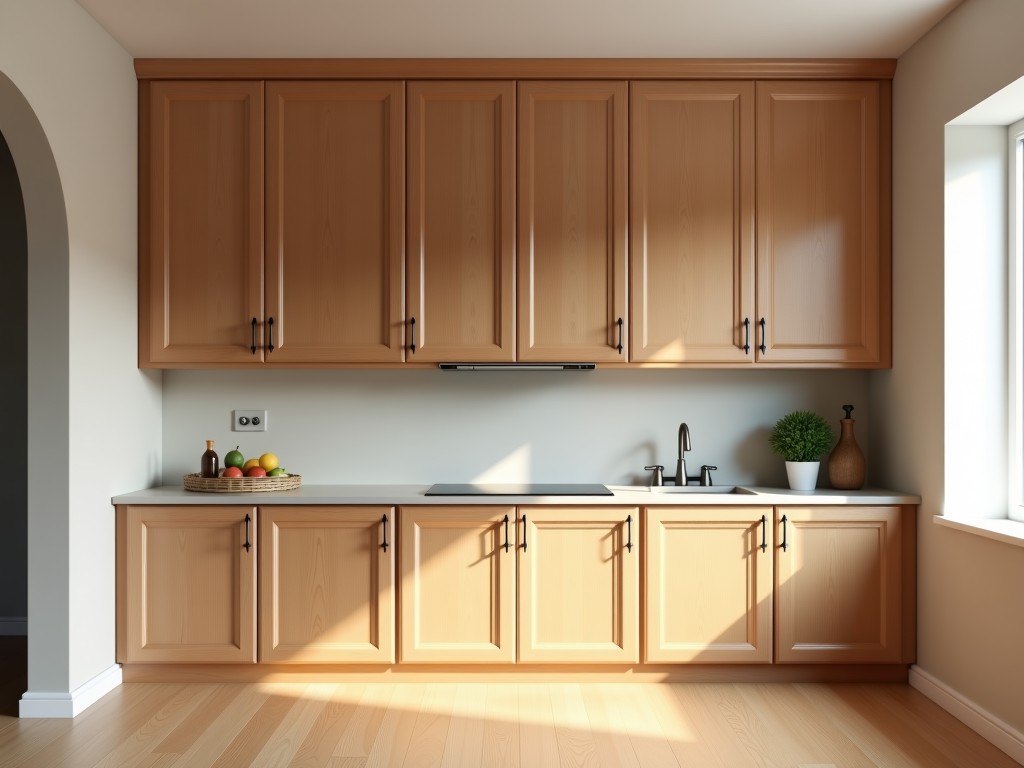
Kitchen Larder Unit Built In Factory
Kitchen Larder Unit Built In Factory
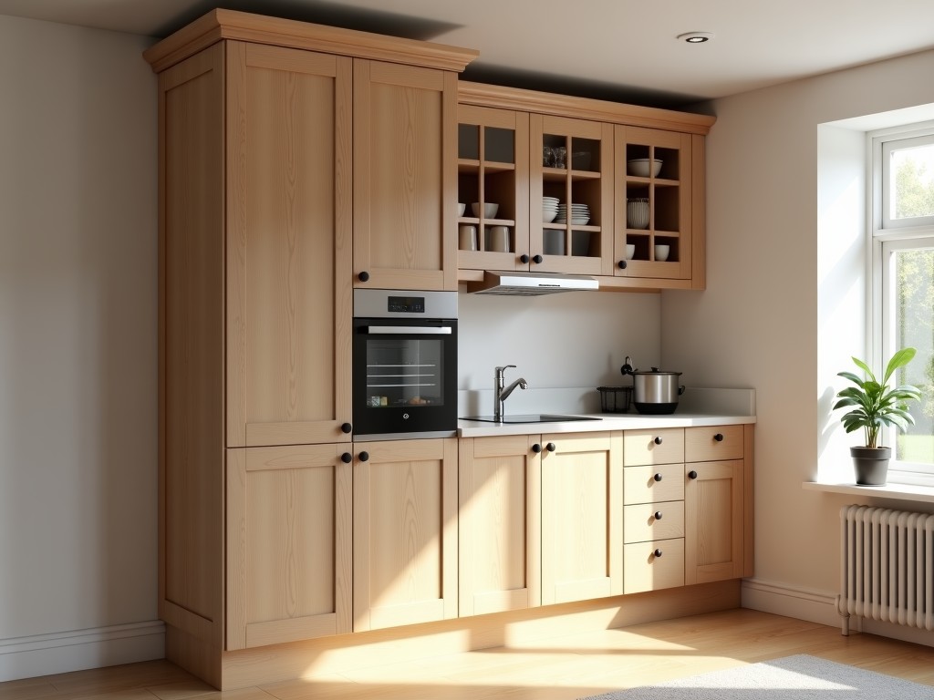
Kitchen Larder Unit Built-In: Engineering Considerations for Integrated Storage
A built-in kitchen larder unit is a fixed storage solution designed to integrate seamlessly within cabinetry runs, providing dedicated, organized space for dry goods, bulk ingredients, and kitchen staples. Unlike freestanding pantries, its integration requires precise dimensional coordination with surrounding structures, influencing material selection, hardware specification, and installation methodology. For procurement managers and design engineers evaluating such units for residential, multi-unit housing, or commercial kitchen projects, understanding the engineering implications—beyond basic dimensions—is essential to ensure long-term functionality, structural compatibility, and ease of maintenance.
Material Selection and Structural Implications
The choice of material directly affects the unit’s weight, dimensional stability, resistance to humidity-induced movement, and compatibility with adjacent cabinetry. Common substrates include:
- Melamine-faced particleboard (MFP): Widely used in modular kitchen systems due to consistent thickness (±0.5 mm typical), smooth finish, and cost-effectiveness. However, it is susceptible to edge swelling if exposed to moisture, making edge sealing critical in high-humidity zones.
- Plywood (birch or poplar core): Offers superior screw-holding strength and resistance to delamination. Cross-laminated construction minimizes warping, making it suitable for taller units or those bearing significant load. Typical thickness ranges from 15–18 mm with tolerances held to ±0.3 mm in precision manufacturing.
- MDF (medium-density fibreboard): Provides excellent surface uniformity for painted finishes but has lower moisture resistance than plywood. Its homogeneity allows for clean routing of shelves and dividers, though it requires careful handling to avoid edge damage during installation.
For environments with fluctuating humidity—such as kitchens adjacent to cooking zones or in tropical climates—material selection must account for equilibrium moisture content (EMC). Specifying materials with low hygroscopic response or applying moisture-resistant barriers (e.g., PVC edge banding, melamine sealing) helps maintain dimensional integrity over time.
Load Distribution and Shelf Design
A larder unit typically stores heavy items like sacks of flour, bulk containers, or appliances. Therefore, shelf load capacity and support spacing are critical design parameters. Shelves spanning 600 mm or more without intermediate support may deflect under load, especially if constructed from lower-density materials.
To mitigate sag:
- Use shelves with a minimum thickness of 18 mm for spans exceeding 500 mm.
- Integrate vertical dividers or intermediate supports to reduce effective span.Specify shelf supports (e.g., metal pins, bored holes with sleeves) that resist pull-out under dynamic load. Steel pins with a minimum diameter of 5 mm and zinc plating are common for corrosion resistance in humid environments.
- Consider adjustable shelving systems with standardized hole patterns (e.g., 32 mm spacing) to allow reconfiguration while maintaining structural integrity.
Load testing should simulate real-world conditions: uniformly distributed loads (UDL) of 20–30 kg per shelf are typical for dry goods, but point loads from heavy appliances may require localized reinforcement.
Dimensional Coordination and Installation Tolerances
Built-in installation demands tight coordination between the larder unit and surrounding cabinetry, walls, and flooring. Even minor deviations can cause binding, uneven reveals, or complications during countertop templating.
Key dimensional considerations include:
- Unit height must align with standard base cabinet height (typically 870–900 mm including legs) or wall cabinet soffits to maintain a continuous countertop plane.
- Depth is usually 550–600 mm to match standard cabinetry, though shallower depths (450–500 mm) may be used in tight spaces, potentially requiring custom door hinges or pull mechanisms.
- Width varies based on storage needs, but common modules are 300, 400, 500, or 600 mm to align with standard cabinet grids. Units wider than 600 mm often require intermediate stiles or mullions to prevent door warping and ensure hinge longevity.
- Clearances for door swing or pull-out mechanisms must account for adjacent appliances, walls, or protrusions. A minimum of 50 mm clearance is recommended for full-access pull-out systems.
Installation tolerances are typically held to ±2 mm for height and width, and ±1.5 mm for depth, to allow for shimming and adjustments without inducing stress on the unit or surrounding structures. These tolerances assume a flat, plumb substrate—any deviation in the wall or floor must be corrected during carcass installation.
Hardware and Accessibility Features
The functionality of a built-in larder unit is heavily influenced by its access mechanism. Options range from traditional hinged doors to full-extension pull-out systems, each with distinct implications for usability, space utilization, and installation complexity.
Pull-out larder systems (often referred to as “pull-out pantries”) use ball-bearing or roller glides to enable complete access to stored items. Key specifications include:
- Dynamic load capacity: Typically 20–40 kg per side, depending on glide quality and module width.
- Extension: Full extension (100%) is standard for accessibility; over-travel or soft-close features add convenience but increase cost.
- Mounting: Side-mounted or bottom-mounted glides; side-mounted systems are more common for narrow units, while bottom-mounted may be preferred for wider modules to reduce racking.
- Glide material: Cold-rolled steel with zinc plating or stainless steel for corrosive environments; nylon rollers may be used in lighter-duty applications but wear faster under load.
For hinged doors, consider:
- Hinge type: Full-overlay, concealed hinges with 3-way adjustment (height, depth, side) are standard for alignment flexibility.
- Opening angle: 110° is typical; 165° or zero-clearance hinges may be needed for corner installations or tight spaces.
- Door weight: Must be calculated based on material, size, and any internal storage (e.g., door-mounted racks). Heavy doors may require soft-close dampers or reinforced hinges to prevent sag.
Typical Specifications Table
| Parameter | Typical Range / Value | Notes |
|---|---|---|
| Unit Height | 870–2100 mm | Base, tall, or pantry-height configurations |
| Unit Width | 300–900 mm | Standard modules; wider units require mid-stiles |
| Unit Depth | 450–600 mm | Matches standard cabinetry depth |
| Shelf Thickness | 15–18 mm | Depends on span and load requirements |
| Shelf Load Capacity (UDL) | 20–35 kg | Uniformly distributed; point loads reduce capacity |
| Pull-Out Dynamic Load | 20–40 kg per side | Depends on glide specification and width |
| Glide Extension | 100% (full extension) | Soft-close or over-travel available |
| Door Hinge Adjustment | 3-way (height, depth, side) | Concealed, full-overlay hinges standard |
| Installation Tolerance (Height/Width) | ±2 mm | Assumes flat, plumb substrate |
| Installation Tolerance (Depth) | ±1.5 mm | Allows for shimming and alignment |
Values in the table represent typical industry ranges for standard configurations. Actual specifications depend on material selection, hardware choice, and project-specific requirements. Custom dimensions, load ratings, or hardware systems are available upon request.
Customization and Project Integration
Built-in larder units are rarely off-the-shelf commodities in professional projects. Their integration demands alignment with architectural plans, electrical layouts, and appliance schedules. Customization options commonly addressed include:
- Non-standard heights to accommodate ceiling variations or bulkheads.
- Modified depths to work around structural elements or achieve specific clearances.
- Internal accessories: spice racks, wine baskets, tray dividers, or door-mounted storage.
- Finish matching: veneer, laminate, or paint to align with surrounding cabinetry.
- Electrical integration: provisions for internal lighting or power outlets (requires compliance with local electrical codes).
For OEMs or developers managing repeatable units, providing detailed CAD models, installation guides, and hardware schedules reduces field errors and ensures consistency across sites. Clear documentation of tolerances, adjustment ranges, and sequencing (e.g., install carcass before countertop templating) is essential for smooth coordination with contractors.
Quality Control and Consistency
Variability in material flatness, edge finish, or hole placement can compromise alignment and long-term performance. Reputable manufacturers implement inline checks for:
- Panel thickness and squareness (±0.2 mm tolerance on diagonal difference).
- Edge banding adhesion and completeness (no bare substrate exposure).
- Bore hole placement accuracy (typically ±0.5 mm for 32 mm system holes).
- Finish uniformity (no color variation, orange peel, or pinholes in painted surfaces).
Packaging for built-in units must protect edges and surfaces during transit. Common methods include corner protectors, edge foam, and shrink-wrapping or cardboard sleeves. Units are typically shipped flat-packed or pre-assembled depending on size and fragility, with assembly instructions and hardware kits included.
Lead times vary based on material availability, finish complexity, and order volume. Standard laminate finishes in common dimensions may ship in 2–4 weeks, while custom veneers, painted finishes, or specialized hardware can extend timelines to 6–8 weeks or more. Expedited options are often available for project-critical items.
When evaluating suppliers, request documentation on material sourcing, process controls, and inspection protocols. Consistency in thickness, finish, and dimensional accuracy reduces installation adjustments and callback rates—key factors in total project cost.
Discuss your project requirements with our engineering team to review material options, load specifications, and integration details for your built-in larder unit application.