Custom Wood Built Ins
Custom Wood Built Ins
Custom Wood Built-Ins: Engineering Solutions for Precision Interior Applications
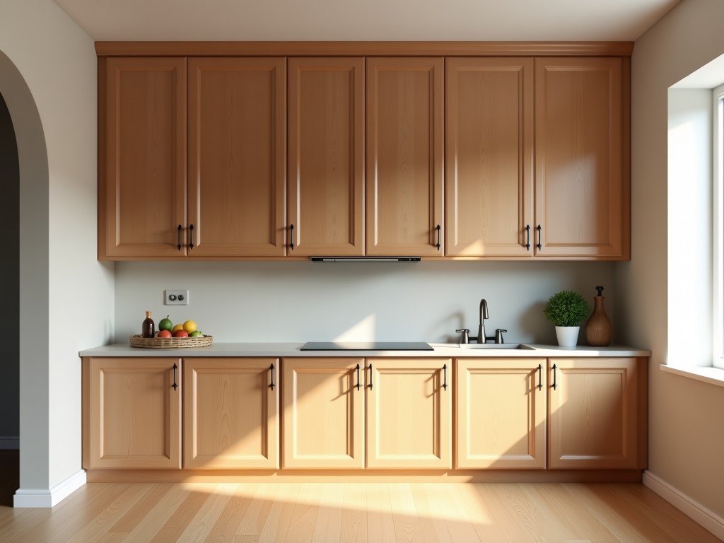
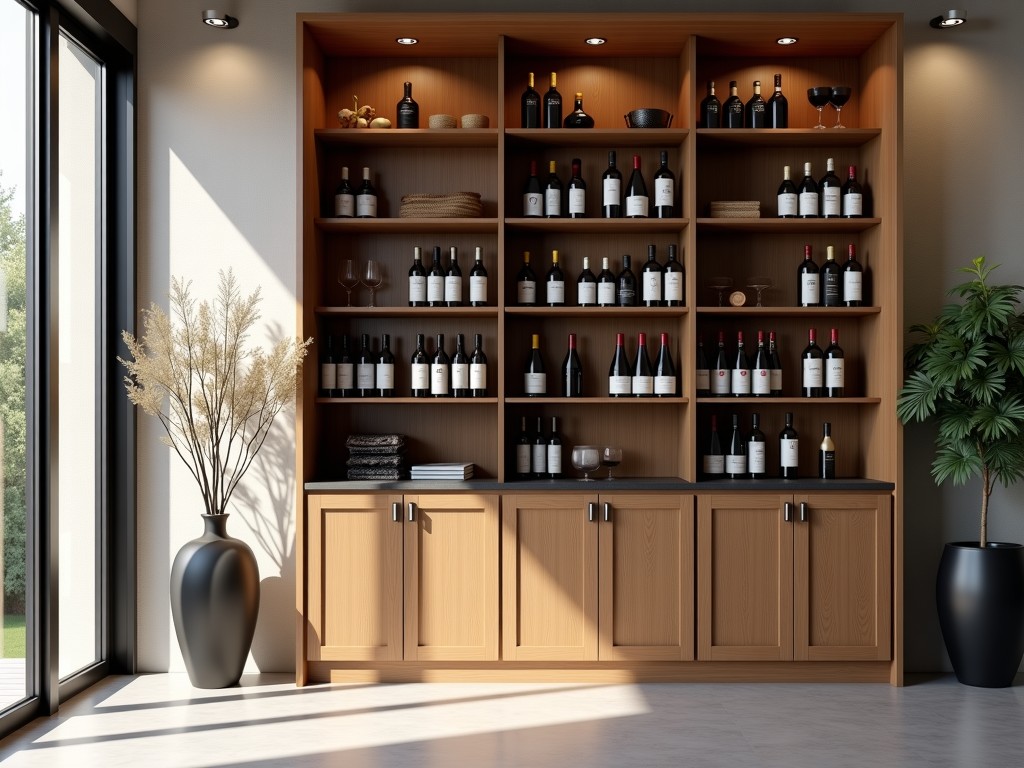
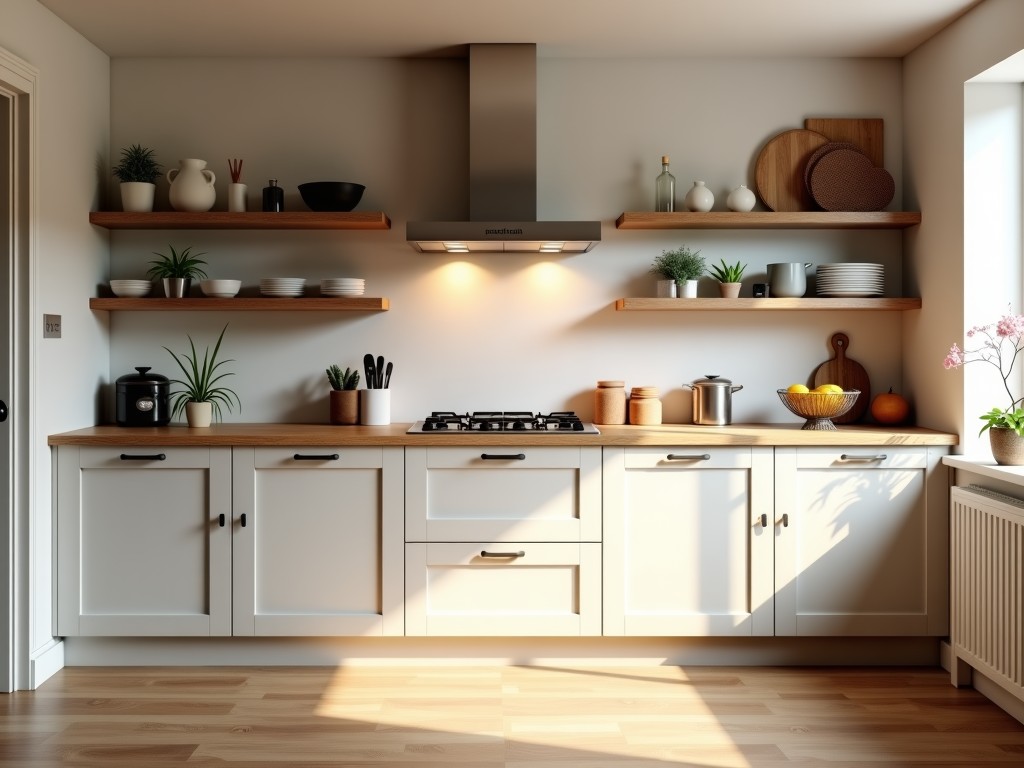
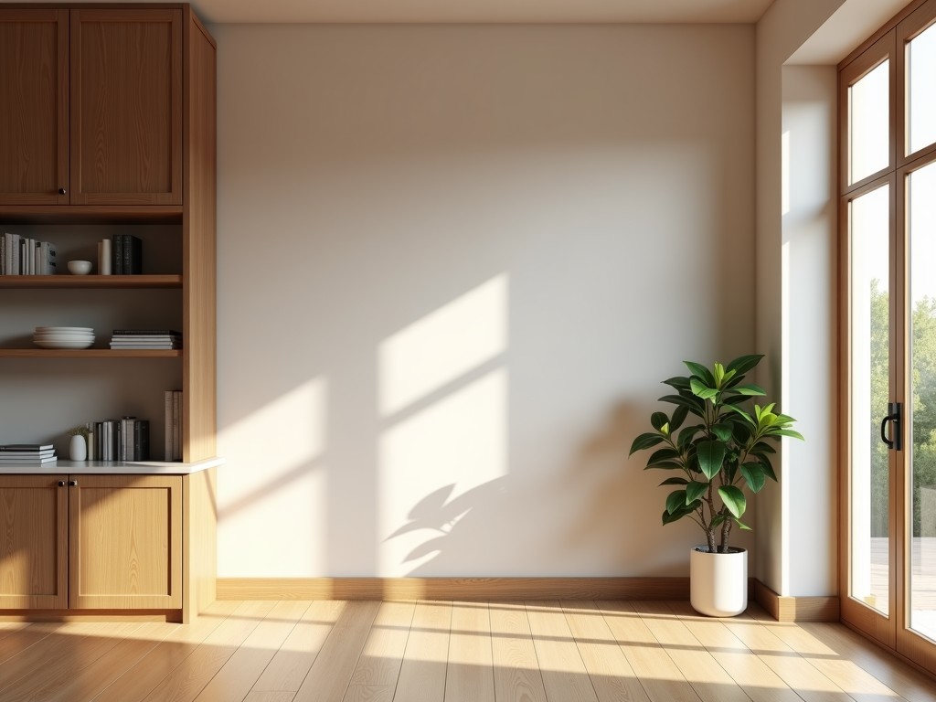
Custom wood built-ins are engineered millwork assemblies designed to integrate seamlessly into architectural spaces while meeting specific functional, dimensional, and aesthetic requirements. Unlike off-the-shelf cabinetry, these systems are developed from project-specific drawings, material selections, and installation constraints to ensure structural stability, finish consistency, and long-term performance in demanding environments.
Industry Challenge: Balancing Design Intent with Manufacturing Constraints
Design teams often face challenges translating complex built-in concepts into manufacturable solutions. Variations in wall substrates, uneven floors, and concealed mechanical penetrations require adaptive framing and joinery strategies. Standard panel products frequently fail to accommodate tight tolerances around appliances, lighting fixtures, or HVAC grilles, leading to field modifications, finish mismatches, or compromised durability. Custom built-ins resolve these issues by incorporating site-specific measurements, material movement allowances, and modular assembly techniques that simplify on-site installation while preserving design integrity.
Engineering Perspective: Material Selection and Dimensional Stability
Material choice directly influences the long-term behavior of built-in assemblies, particularly in environments with fluctuating humidity or thermal cycling. Solid hardwoods offer superior rigidity and finish depth but require careful acclimatization and joinery to manage seasonal movement. Engineered substrates like MDF or plywood provide enhanced dimensional stability for large panels, reducing the risk of warping or telegraphing through finishes. For high-moisture areas such as bathrooms or kitchens, moisture-resistant core materials with sealed edges and compatible finishes prevent delamination and fungal growth.
Manufacturing Process: From Digital Template to Finished Assembly
Production begins with validated CAD models that incorporate wall surveys, service clearances, and finish layers. CNC routing ensures repeatable precision for dadoes, rabbets, and hardware pockets, while edge banding or solid wood lipping protects vulnerable surfaces. Assembly utilizes mechanical fasteners, adhesives, and floating panels to accommodate substrate movement without inducing stress. Each unit undergoes dry-fit verification before finish application to confirm alignment, reveal consistency, and hardware operability.
Typical Specifications
| Parameter | Typical Range / Notes |
|---|---|
| Panel Thickness | 12mm to 25mm (solid wood); 16mm to 19mm (engineered core) |
| Overall Depth | 300mm to 600mm (adjustable for services) |
| Height Increment | 50mm module (customizable to site conditions) |
| Joinery Tolerance | ±0.5mm for visible reveals; ±1.0mm for concealed joints |
| Finish Thickness | 0.1mm to 0.3mm (catalyzed lacquer, polyurethane, or veneer) |
| Edge Treatment | Solid wood lipping, PVC edge band, or radiused solid wood |
| Mounting Method | Cleat systems, French cleats, or direct screw-to-stud with shims |
Application Scenarios: Where Precision Matters
In healthcare facilities, custom built-ins support infection control protocols through seamless surfaces, integrated waste solutions, and non-porous finishes that withstand aggressive cleaning agents. Retail environments utilize them for branded fixture integration, where lighting channels, display risers, and security components must align with millwork tolerances to maintain visual merchandising standards. Educational institutions specify durable, impact-resistant constructions for high-traffic zones, incorporating reinforced shelving and anti-tip mechanisms compliant with safety codes.
Customization Options: Beyond Standard Configurations
Customization extends beyond dimensions to include specialized hardware integration (soft-close mechanisms, electronic locks, motorized lifts), embedded power/data routing, and acoustic treatments for media rooms or studios. Finish systems can be tailored to match existing architecture through custom staining, glazing, or color-matching to RAL or NCS standards. For projects requiring rapid reconfiguration, modular framing systems with interchangeable panels allow future modifications without demolishing surrounding finishes.
Quality Control and Inspection Protocols
Dimensional verification occurs at multiple stages: post-CNC machining, pre-finish assembly, and final packaging. Surface quality is assessed under standardized lighting to detect telegraphing, sanding marks, or finish adhesion issues. Hardware functionality is cycle-tested where applicable, and edge integrity is checked for uniform adhesion and radius consistency. All units are labeled with project identifiers and include installation schematics highlighting shim locations, service access points, and load-bearing zones.
Packaging and Logistics Considerations
Assemblies are packaged using corner protectors, edge guards, and vapor barriers to prevent finish damage and moisture ingress during transit. Large units are broken down into sub-assemblies with clearly marked mating surfaces and hardware kits to simplify on-site reconstruction. Flat-pack options are available for remote installations, utilizing cam locks and alignment pins to maintain precision without specialized tools. Each package includes a packing list referencing CAD revision numbers and material batch codes for traceability.
Selection Guide: What Procurement Teams Should Evaluate
When evaluating suppliers, request documentation on material acclimatization procedures, finish system compatibility with specified environments, and references for similar complexity projects. Inquire about their capacity to handle field measurements, manage change orders during construction, and provide spare touch-up kits matched to production batches. Confirm whether their workflow includes BIM coordination or shop drawing review to prevent clashes with structural or MEP elements before fabrication begins.
Frequently Asked Questions
What file formats are required for quotation?
Clean CAD files (DWG, DXF, or SKP) with wall elevations, section details, and finish schedules are preferred. PDFs can be used for initial review but may require clarification for complex geometries.
How are variations in wall plumbness accommodated?
Built-in systems incorporate adjustable mounting cleats, scribe filler strips, or shim-compatible rail systems to adapt to out-of-plumb conditions without inducing panel stress or visible gaps.
Can existing electrical or plumbing rough-ins be integrated?
Yes. Service penetrations are modeled during design, with framed openings, grommets, or removable access panels provided to maintain finish integrity while allowing future access.
What is the typical lead time for production?
Lead times range from 4 to 6 weeks after drawing approval and material selection, depending on complexity, finish system, and current capacity. Expedited options are available for critical-path items.
Are samples or finish swatches available?
Finish samples and material coupons can be provided upon request, typically within 3–5 business days. Large finish panels are available for projects requiring full-scale visual validation.